Cart is empty.


Test and Inspection of Self-Regulating and Power-Limiting Heating System Cables
Visual Inspection
- Check inside heating cable components for proper installation, overheating, corrosion, moisture, and loose connections.
- Check the electrical connections to ensure that ground and bus wires are insulated over their full length.
- Check for damaged or wet thermal insulation; damaged, missing or cracked lagging and weather-proofing.
- Check that end seals, splices, and tees are properly labeled on insulation cladding.
- Check control and monitoring system for moisture, corrosion, set point, switch operation and capillary damage.
Insulation Resistance (Megger) Test
Frequency
Insulation resistance testing is recommended at five stages during the installation process and as part of regularly scheduled maintenance.
- Before installing the cable
- Before installing components
- Before installing the thermal insulation
- After installing the thermal insulation
- Prior to initial start-up (commissioning)
- As part of the regular system inspection
- After any maintenance or repair work
Procedure
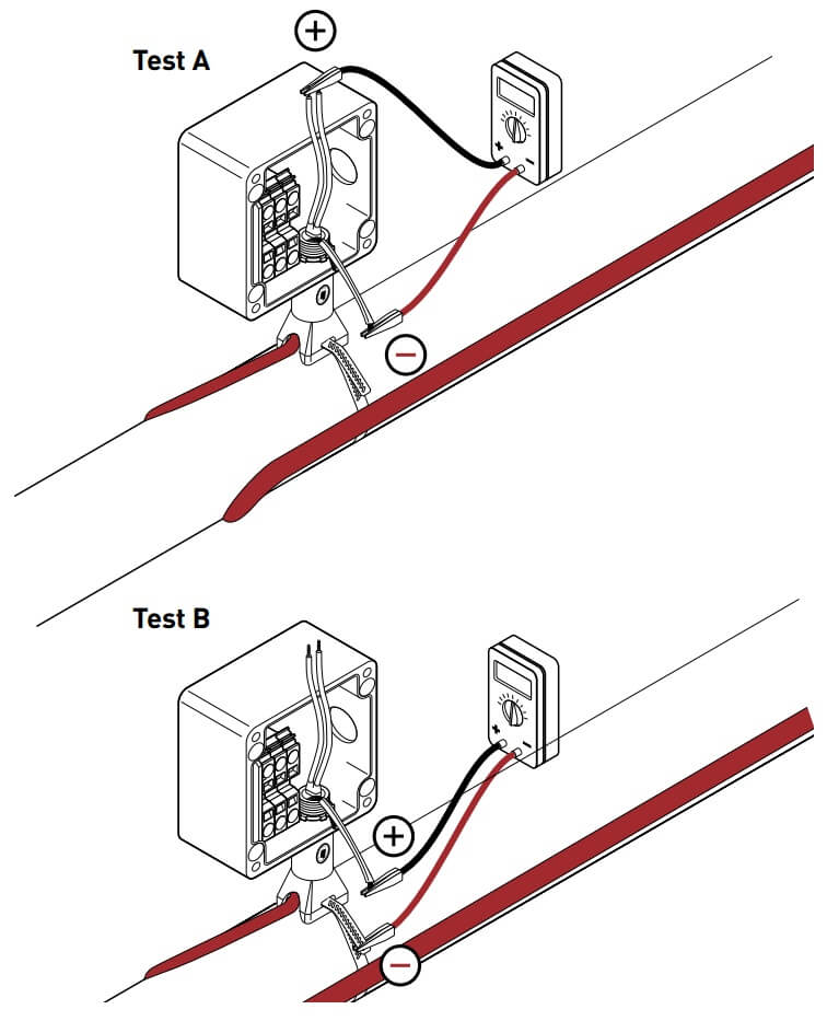
Insulation resistance testing (using a megohmmeter) should be conducted at three voltages; 500, 1000, and 2500 Vdc. Significant problems may not be detected if testing is done only at 500 and 1000 volts.
First measure the resistance between the heating cable bus wires and the braid (Test A) then measure the insulation resistance between the braid and the metal pipe (Test B). Do not allow test leads to touch junction box, which can cause inaccurate readings.

- De-energize the circuit.
- Disconnect the thermostat or controller if installed.
- Disconnect bus wires from terminal block, if installed.
- Set test voltage at 0 Vdc.
- Connect the negative (–) lead to the heating cable metallic braid.
- Connect the positive (+) lead to both heating cable bus wires simultaneously.
- Turn on the megohmmeter and set the voltage to 500 Vdc; apply the voltage for 1 minute. The meter needle should stop moving. Rapid deflec- tion indicates a short. Record the insulation resistance value in the Inspection Record.
- Repeat Steps 4–7 at 1000 and 2500 Vdc.
- Turn off the megohmmeter.
- If the megohmmeter does not self-discharge, discharge phase connection to ground with a suitable grounding rod. Disconnect the megohmmeter.
- Repeat this test between braid and pipe.
- Reconnect bus wires to terminal block.
- Reconnect the thermostat.
 Important: System checkout and regular main- tenance procedures require that insulation resistance testing be performed from the distribution panel unless a control and monitoring system is in use. If no control system is being used, remove both power feed wires from the breaker and proceed as if testing heat- ing cable bus wires. If a control and monitoring system is being used, remove the control equipment from the circuit and conduct the test directly from the heating cable.
WARNING: Fire hazard in hazardous locations. The insulation resistance test can produce sparks. Be sure there are no flammable vapors in the area before performing this test.
Insulation Resistance Criteria
A clean, dry, properly installed circuit should mea- sure thousands of megohms, regardless of the heat- ing cable length or measuring voltage (0–2500 Vdc). The following criteria are provided to assist in deter- mining the acceptability of an installation where optimum conditions may not apply.
All insulation resistance values should be greater than 1000 megohms. If the reading is lower, consult Section 10, Troubleshooting Guide.
 Important: Insulation resistance values for Test A and B; for any particular circuit, should not vary more than 25 percent as a function of measuring voltage. Greater variances may indicate a problem with your heat-tracing system; confirm proper installation and/ or contact Pentair Thermal Management for assis- tance.
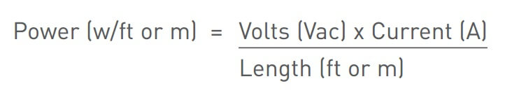
Power Check
The power output of Self-Regulating and Power- Limiting cable is temperature-sensitive and requires the following special procedure to determine its value.
- Power the heating cable and allow it to stabilize for 10 minutes, then measure current and voltage at the junction box. If a thermostat or controller is used, refer to details below.
- Check the pipe temperature under the thermal insulation at several locations.
- Calculate the power (watts/ft) of the heating cable by multiplying the current by the input voltage and dividing by the actual circuit length.
Ambient-sensing controlled systems
If the actual ambient temperature is higher than the desired thermostat setting, turn the thermostat set- ting up high enough to turn on the system, or (with some models) manually set the selector switch to the ON position.
- Turn on the main circuit breaker.
- Turn on the branch circuit breakers.
- After a minimum of ten minutes, measure the volt- age, amperage, ambient temperature, and pipe temperature for each circuit and record the values in the “Installation and Inspection Record” (refer to Section 11). This information is needed for future maintenance and troubleshooting.
- When the system is completely checked out, reset the thermostat to the proper temperature
Line-sensing controlled systems
Set the thermostat to the desired control tempera- ture, or to a setting high enough to turn the circuit on if the pipe temperature is above the control temperature.
- Turn on the main circuit breaker.
- Turn on the branch circuit breakers.
- Allow the system to reach the control point. This may take up to four hours for most circuits. Large, liquid-filled pipes may take longer.
- Measure the voltage, amperage, and pipe tem- perature for each circuit and record the values in the “Installation and Inspection Record” (refer to Section 11). This information is needed for future maintenance and troubleshooting.
- When the system is completely checked out, reset the thermostat to the proper temperature.
Control and monitoring systems
Refer to the installation instructions supplied with the product for commissioning tests and records.
Fault Location Tests
Fault location
There are three methods used for finding a fault within a section of heating cable: the ratio method, 1/R method, and the capacitance method. The capacitance method can also be used to determine total heating cable length.
Ratio Test Method
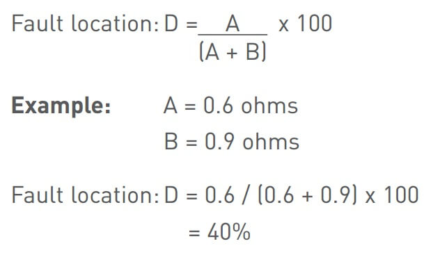
a.) To locate bus wire short:
The ratio method uses resistance measurements taken at each end of the heating cable to approxi- mate the location of a bus wire short. A shorted heating cable could result in a tripped circuit break colder or a Braid section of pipe.
Measure the bus-to-bus conductor resistance from the front end (measurement A) and the back end (mea- surement B) of the suspected section.
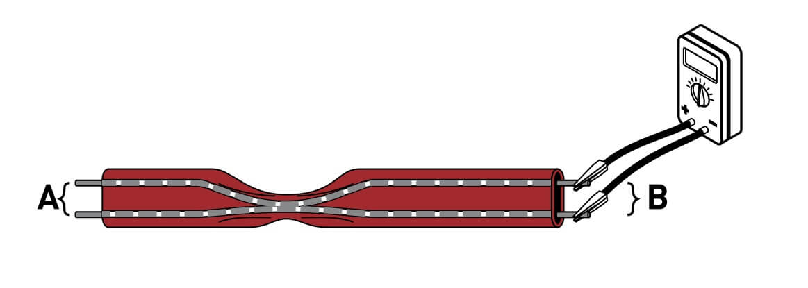
The approximate location of the bus wire short, expressed as a percentage of the heating cable length from the front end, is:
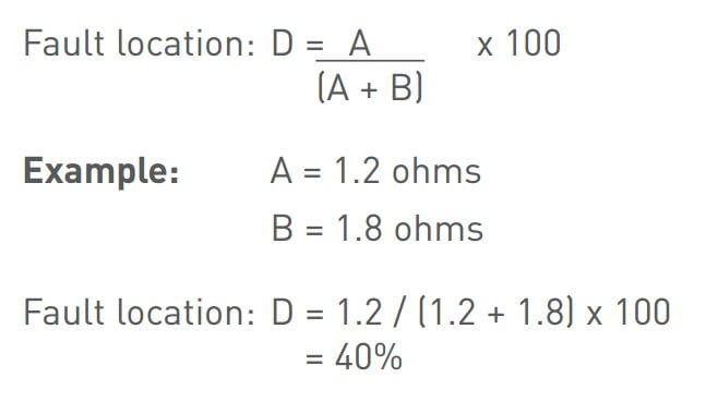
The fault is located 40% along the circuit as measured from the front end (A).
b.) To locate low resistance ground fault:
To locate a low resistance ground fault, measure resistance between bus and braid.
The approximate location of the fault, expressed as a percentage of the heating cable length from the front end (A), is:
The fault is located 40% along the circuit as measured from the front end (A).
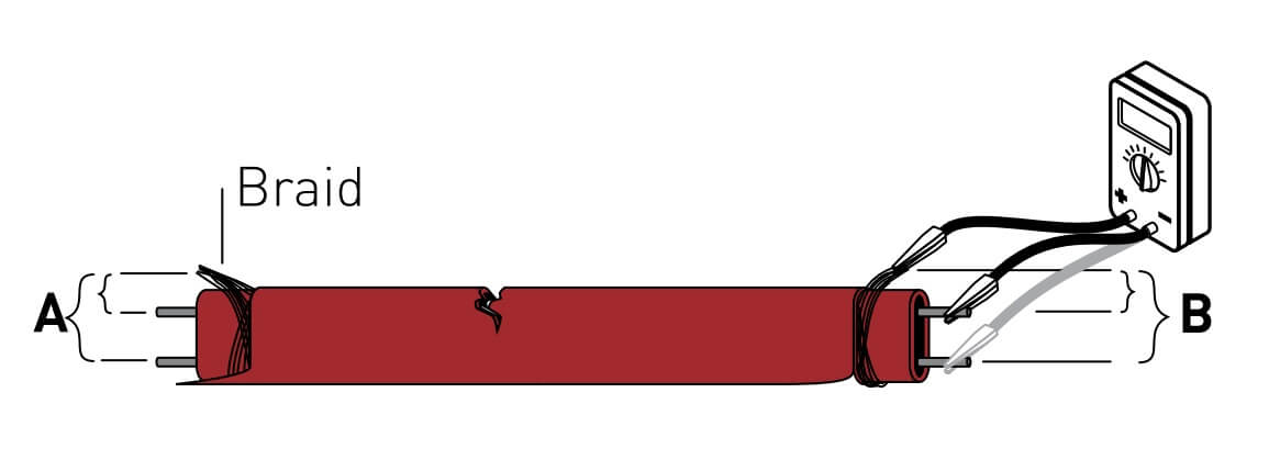
c.) To locate severed section:
This method uses the core resistance of the heating cable to approximate the location of a fault when the heating cable has been severed and the bus wires have not been shorted together. A severed cable may result in a cold section of pipe and many not trip the circuit breaker.
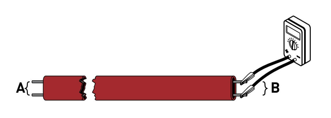
Measure the bus-to-bus heating cable resistance from the front end (measurement A) and the back end (measurement B) of the suspect section.
The approximate location of the fault, exprBessed as a percentage of the heating cable length from the front end (A) is:
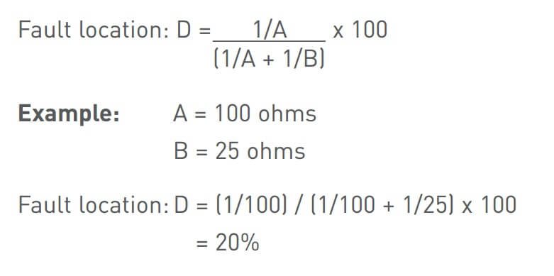
The fault is located 20% from the front end (A) of the circuit.
Capacitance Test Method
This method uses capacitance measurement (nF) to approximate the location of a fault where the heating cable has been severed. It also gives an estimate of total heating cable length in a non-severed circuit. This reading must be taken at the power connection and will only work when the heating cable has passed IR testing. This information is used to calculate the heating cable output per linear foot or to determine if the maximum length has been exceeded.
Record the capacitance reading from one end of the heating cable. The capacitance reading should be measured between both bus wires twisted together (positive lead) and the braid (negative lead).
Multiply the measured capacitance with the heating cable’s capacitance factor as listed in the following table.
Example:
20XTV2-CT
Recorded capacitance = 16.2 nF
Capacitance factor = 10.1 ft/nF
Fault location = 16.2 x 10.1 nF
= 164 ft (50 m)
from reading location
As an alternative, capacitance values from both the front and back end can be used. The ratio of one capacitance value taken from one end (A) divided by the sum of both A and B (A + B) and then multi- plied by 100 yields the distance from the first end, expressed as a percentage of the heating circuit length.
Heating cable capacitance factors
|
Cable catalog number |
Capacitance factor |
Cable catalog number |
Capacitance factor |
|
3BTV1-CR |
7.5 |
15QTVR1-CT |
3.3 |
|
3BTV2-CT |
|
20QTVR1-CT |
|
|
3BTV1-CR |
|
20QTVR2-CT |
|
|
3BTV2-CT |
|
5XTV1-CT-T3 |
10.8 |
|
5BTV1-CR |
7.5 |
5XTV2-CT-T3 |
11.1 |
|
5BTV2-CT |
|
10XTV1-CT-T3 |
10.3 |
|
5BTV1-CR |
|
10XTV2-CT-T3 |
10.7 |
|
5BTV2-CT |
|
15XTV1-CT-T3 |
9.7 |
|
8BTV1-CR |
5.5 |
15XTV2-CT-T3 |
9.9 |
|
8BTV2-CT |
|
20XTV1-CT-T2 |
9.3 |
|
8BTV1-CR |
|
20XTV2-CT-T2 |
10.1 |
|
8BTV2-CT |
|
5KTV1-CT |
10.8 |
|
10BTV1-CR |
5.5 |
5KTV2-CT |
11.1 |
|
10BTV2-CT |
|
8KTV1-CT |
10.3 |
|
10BTV1-CR |
|
8KTV2-CT |
10.5 |
|
10BTV2-CT |
|
15KTV1-CT |
9.7 |
|
10QTVR1-CT |
4.7 |
15KTV2-CT |
9.9 |
|
10QTVR2-CT |
|
20KTV1-CT |
9.3 |
|
15QTVR2-CT |
|
20KTV2-CT |
10.1 |
|
|
|
All VPL-CT |
9.4 |


