عربة التسوق فارغة.

هي وصلات من الكابلات(patch cord) لربط أجهزةالشبكة بمقبس الشبكة الجداري (jack face plate)، فالباتش كورد يسمح بقدر من المرونة في التركيب النهائي. ممايساهم بقدر معقول من تحديد المسافات بين المقابس الجدارية – وطاولة المكتب (طاولة الحاسب الآلي).
Quality
The quality of patch cords is governed by industry specifications. The two most common are EIA/TIA-568-B.31) and Telcordia GR-326-CORE2). 568-B.3 was written for commercial enterprise building applications, including office and campus environments, where both singlemode and multimode networks can be
deployed. GR-326-CORE was written as part of Telcordia’s General Requirements series to be consistent with the Telecommunications Act of 1996. It was intended for use in the service provider markets, which are predominantly long haul high-speed applications such as telecommunications and cable TV. In this market, the requirement is singlemode, so this specification has no provisions for multimode patch cords.
Each specification details a series of environmental and mechanical tests. There is overlap in the type of testing performed in GR-326-CORE and 568-B.3. Nearly all of the individual tests in 568-B.3 have counterparts in GR-326-CORE and these tests make up the majority of the section of GR-326 referred to as “Service Life” testing.
The function of the Service Life tests is to simulate the stresses a connector may experience during its lifetime. GR-326-CORE also encompasses an additional set of tests that have no equivalent in 568-B.3. These are referred to as “Reliability Tests” and their purpose is to identify potential shortcomings in the design and materials of the connector across a range of service environments. Service Life testing is sequential, which requires that the entire sample population be subjected to every test in a
specified order. On the other hand, a new sample population may be submitted for each of the Reliability Tests, just as they may with each test in 568-B.3.
The testing in these specifications is not done on 100% of production. These tests are usually performed periodically over years to assure that the components and manufacturing procedures can produce the proper quality level of patch cords.
Environmental Testing
Both specifications include a battery of environmental tests, each of which denotes the specific temperatures and conditions the connectors must be subjected to for prolonged periods. As these are Service Life tests, GR-326-CORE requires the testing be performed in a specific sequence.
These tests are not performed to ensure the patch cords will be able to withstand prolonged exposure to 85°C or temperature fluctuations of up to 125°C. The purpose of these tests is to simulate the effects of aging on patch cords in various environments. By subjecting the connector to excessive temperature extremes, the test is designed to cause expansion and contraction of all the different materials of the terminated connector. Epoxy, metal, ceramic, glass, and, in some cases, polymers will intersect at a single juncture just behind the ferrule.
At higher temperatures, these materials will expand at their own intrinsic rates, inducing various strains on the components. If the test is a thermal cycle, where the temperature fluctuates over an expansive range, the test becomes more extreme. Thermal cycling involves changing the ambient temperature of the connector by 125°C every 2 to 4 hours.
Heavy stresses and strains will be induced on each of the materials involved. This test will also expose any weaknesses in the termination. If
the design and procedures are not optimal, this can lead to fiber movement or “pistoning” within the ferrule, or in extreme cases, fiber cracks or breakage.
Humidity testing is designed to introduce moisture into the system and, as the test is performed at elevated temperatures, to simulate the effects of long-term exposure. Exposure to moisture or water can be very harmful to glass optical fiber, and prolonged exposure can cause the fiber to become brittle and more susceptible to stresses, a condition known as fiber “decay”3).
Mechanical Testing
There are several mechanical tests required in these two primary specifications. These include: Flex Testing, Twist Testing, Proof Testing, Cable Retention, Impact Testing, Vibration Testing, Durability, and Transmission with an Applied Load. The detailed requirements vary slightly between the two specifications, but the general procedures and concepts remain the same.
Many of these mechanical tests confirm that the patch cord can survive the installation and maintenance performed. Testing such as Cable Retention, which is part of 568-B.3, is to ensure the terminated patch cord will withstand the pulling forces incurred during installation. Proof Testing, the equivalent in GR-326-CORE, is similar to Cable Retention, and also ensures the strength of the latching mechanism of the connector. Should the patch cord receive a sudden tug after installation, this test ensures that the patch cord will neither break nor pull out of the adapter. 568-B.3 has a separate test called “Strength of Coupling Mechanism” for this criterion.
The only other test that attempts to duplicate installation problem is Impact Testing. Impact Testing is performed to verify that connectors are not damaged when they are dropped.
Flex, Twist, Vibration, and Transmission with an Applied Load tests are all performed to simulate stresses on the terminated cable and mated connector that could be incurred over the life of the connector. Connectors subjected to physical extremes are then verified optically to ensure the quality of the termination. In GR-326-CORE, many of these connectors are “pre-stressed” after concluding the environmental portion of the sequence. Weaknesses in the components or termination procedures are usually exposed during mechanical testing due to these stresses.
Durability testing is also designed to simulate the repeated use of a connector. This test involves continually inserting the connector into the adapter or jack. The test can potentially reveal any design and material flaws in the connector, such as any portion of the latching mechanism that becomes heavily
strained or flawed by frequent use.
Reliability Testing
The criteria on these tests are exclusive to Telcordia GR-326-CORE. The testing includes exposure to a variety of environments, including additional environmental testing and exposure testing.
The additional environmental tests include extended versions of the Thermal Life, Humidity, and Thermal Cycle. These tests, which run for 2000 hours each (83 days), are further studies in the life of the connector across a range of service environments. Testing is non-sequential, so there is no cumulative effect. In the Service Life environmental testing, the sample includes both pigtail assemblies and jumper assemblies, as defined by the specification. These extended tests are limited to jumper assemblies. The rationale for using jumper assemblies is to test for Temperature Induced Cable Loss (TICL). TICL is caused by cable shrinkage from prolonged exposure to elevated temperatures followed by exposure to lower temperatures.
Many of the extruded compounds used in jacketing and buffering will shrink after exposure to elevated temperatures, which can cause micro bending in the glass fibers and induce excessive loss. The tests are monitored using a 1550nm source only, as micro bending is more easily detected using longer wavelengths.
The exposure tests include Dust, Salt Fog, Airborne Contaminants, Ground Water Immersion, and Immersion/Corrosion. Dust can seriously impair optical performance. Particles that contaminate endface can block optical signals and induce loss. Whether or not the dust particles find an exposed path to a ferrule endface is largely a matter of probability. Over time, dust particles will find their way to the optical connection if it is possible.
While the dust particles are not difficult to remove, the cleaning process involves disconnecting the connector, which not only stops the transmission, but also exposes the endface to additional risk of contamination. This test involves intense exposure to a dust of specified size particles in order to determine if there is a risk of any particle finding its way to the ferrule endfaces.
Salt Fog (referred to as Salt Spray) is performed to guarantee the performance of the patch cord in freebreathing enclosures near the ocean. This test involves exposing the connector to a high concentration of NaCl over an extended period. After the test, optical testing is performed, followed by a visual inspection to confirm that there is no evidence of corrosion on the materials.
The Airborne Contaminants test is designed to guarantee the performance and material stability of connectors in outdoor applications with high concentrations of pollution. The test repeatedly exposes mated and unmated connectors to various gases and inspects the connector not only optically, but also performing the same visual examination as in the Salt Fog test. An assortment of volatile gases is used in a small chamber for 20 days to simulate prolonged exposure to these elements.
The materials are also verified in the Immersion/Corrosion test. This test has no optical requirements, but instead involves a prolonged submersion in uncontaminated water. This test, like Dust, Salt Fog, and Airborne Contaminants, involves both mated and unmated connectors. Mated connectors are checked for ferrule deformation by measuring the Radius of Curvature before and after the test, and comparing the values. If the ferrule is not geometrically stable during this test, it could be an indication of a flaw in the zirconia material used in the ferrule. Unmated connectors are checked for Fiber Dissolution, which involves checking to see if the fiber core has not recessed too far into the fiber cladding.
The final exposure test is Groundwater Immersion. This test verifies the ability of the product to withstand underground applications. The Immersion/Corrosion test is strictly to verify the materials involved, and uses de-ionized or distilled water. Connectors deployed in underground environments are much more likely to be exposed to contaminated mediums if their enclosures fail. During this test, the connector is exposed to a
variety of chemicals found in sewage treatment and agricultural fertilization, among other applications, as well as biological mediums. These chemicals include ammonia, detergent, chlorine, and fuel. Presence of these chemicals can have a detrimental effect on the materials comprising the connector and adapter, reducing optical performance.
Biological contaminants include exposure to various organisms, including Streptococcus salivarius, and Escherichia coli. Presence of these bacteria is to more accurately duplicate the true exposure to outdoor environments. These bacteria would also become attracted to and sustained by any growths on the connector over time, creating a potential health risk.
Reliability
Patch cord reliability is guaranteed not only by using quality components and manufacturing processes and equipment, but also by adherence to a successful Quality Assurance program4). While patch cords themselves are typically tested 100% for insertion loss and return loss, if applicable, there are many other factors that need to be monitored to insure the quality of the patch cord.
One of the most important factors is the epoxy. Epoxies typically have a limited shelf life and working life, or “pot life.” This information is readily available from the manufacturer. It is absolutely necessary that both of these criteria be verified and maintained during manufacture. Epoxy beyond its expiration date needs to be discarded. Chemical changes affecting the cured properties of the epoxy can occur after this date. This date can also be dependent on storage conditions, which need to be observed.
Most epoxies used in fiber optic terminations are two-part epoxies and, while they cure at elevated temperatures, preliminary cross-linking will begin upon mixing. Once this has started, the viscosity of the epoxy can begin to change, making application more difficult over time. The epoxy can become too thick to fill the ferrule properly and too viscous to enable a fiber to penetrate, causing fiber breakage.
Mixing two-part epoxies introduces trapped air, or "bubbles", which is injected into the connector. This trapped air introduces inconsistency in the cured epoxy, leading to a high risk of mechanical failure. The trapped air, or bubble count, must be minimized.
Many of the tooling used in patch cord assembly also has periodic maintenance and a limited tool life. This includes all stripping, cleaving and crimping tools. Most stripping tools, whether they are hand tools or automated machines, can be damaged by the components of the cable, most notably the aramid yarn strength members. Buffer strippers will dull with prolonged usage, increasing the likelihood that they will not cleanly cut the buffer.
This can lead to overstressing the fiber when the buffer is pulled off. When a cleaving tool wears out and a clean score is not made, it is almost impossible to detect during manufacturing. However, the result could be non-uniform fiber breakage during the cleave, which can result in either breaking or cracking the fiber below the ferrule endface. In this instance, the connector will have to be scrapped. Even crimp tools require periodic maintenance to insure the proper forces and dimensions are consistent. Crimp dies also have a tendency to accrue epoxy build-up, which can affect the crimping dimensions and potentially damage the connector.
The integrity of the incoming materials and manufacturing processes, once specified, needs to be adhered to all the appropriate guidelines and procedures. The importance of these materials not only has a strong influence on product reliability, but also on product performance.
Performance
Understanding the performance of a patch cord can best be related by not only understanding the importance of the parameters involved, but also by understanding the limitations of the final product. In order to draw conclusions about the specifications, technologies and procedures for a patch cord, it will be useful to model a “perfect patch cord” as defined below.
“Perfect Patch Cord”
A “perfect patch cord” is defined as one with near zero insertion loss, a relative power loss made by a mated pair of connectors. The performance of a “perfect patch cord” must be comparable with fiber splicing loss that is on the order of 0.02dB. A “perfect patch cord” is defined to meet insertion loss <0.05dB and return loss >58dB.
To make a “perfect patch cord”, the best available fiber, ferrule, and test equipment are required. The model of the “perfect patch cord” will be made by singlemode components, because of the tighter material requirements and specifications involved.
There are many parameters that can affect patch cord performance. To make a “perfect patch cord”, the endface geometry of the ferrule must be controlled and a proper polishing process must be followed. The endface must also be kept clean. This makes cleanliness of the production line and the cleaning technique very important.
Loss is reduced by properly aligning the fiber cores within the ferrules of two mated patch cords. The primary factors that influence core alignment are ferrule inner diameter, ferrule concentricity, and ferrule outside diameter (OD). Identifying all relevant parameters and controlling them are the keys to making a “perfect patch cord”.
The final fiber-core-to-ferrule-OD concentricity, or connector concentricity, is the vector sum of all the misalignments. This is one of the most important parameters in defining a “perfect patch cord”. A “perfect patch cord” must have sub-micron connector concentricity. Figure 1 relates insertion loss with connector concentricity.
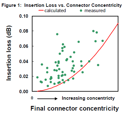 The curve in Figure 1 is calculated insertion loss expected solely by connector concentricity. A
simulation using the component parameters to estimate insertion loss matched well with the available
data from measurements. The reference cable, especially the far end of the cable (Ref end), is always very critical to the measurement of insertion loss and return loss of a connector on a PUT (patch cord under test).
Techniques applied to the “perfect patch cord” can be used in making reference cables. A reference cable to
be used to test optical performance must be superior to the connectors on a patch cord to be tested. The
length of the reference cables and the “perfect patch cords” should be long enough to avoid any effect of
the distribution of light intensity across the fiber core on insertion loss. A length of at least three meters is
recommended.
Testing of a “perfect patch cord” requires a reference cable that is at least comparable to the “perfect patch cord”. Other factors need to be controlled when testing the “perfect patch cord” in order to guarantee accurate measurements. It is important to use a reliable and repeatable test meter. Normal test meter variation of 0.05dB is too great for testing “perfect patch cords”. It is also important to use a high quality adapter to mate the connector to the reference cable. The adapter used in the testing is very important to insure a consistent insertion loss. The adapter can contribute a variation on the order of 0.02dB of insertion loss, which is also too high for “perfect patch cords”. Variations in the insertion loss of a mated pair have been observed based on the orientation of the split in the split sleeve relative to the adapter key. An adapter with the highest reliability must be used and proper cleanliness must be observed.
Polishing
Polishing is a very important ingredient in making the “perfect patch cord”. It determines the connector endface condition and geometry. Polishing can be done one connector at a time by hand, or single or multiple connectors by a machine polisher.
Polishing connectors involves grinding the endface on microscopic grits to remove excess epoxy from the surface and scratches from the fiber endface, as well as shaping the ferrule and glass. Both hand and machine polishing typically use de-ionized or distilled water, which acts similarly to a cutting fluid.
Hand polishing is slow and the results can be operator dependent, while machine polishing is advantageous for consistency and speed. There are a variety of fiber optic polishers available. One cannot expect the same quality of polishing on a polisher from one manufacturer to another.
Most of the current ceramic ferrules are pre-domed; i.e., the endface is shaped to have an optimum radius of curvature (ROC) and smallest possible apex offset (AO), as shown in Figure 2. Apex offset is an offset of the apex point of ROC. In such case, the polishing must use a polishing grit hard enough to remove the epoxy from the ferrule and the scratches on the fiber endface, but not hard enough to significantly alter the ferrule geometry. If a ferrule is not pre-domed, the proper geometry must be formed through extended polishing.
 Polishing is done in a multi-step process. This process is specified with polishing films, times, and pressures. The procedure usually consists of the following steps: initial step to remove epoxy from the ferrule front surface, then form or keep the dome, and the final step is to shine the fiber surface. Depending on the polisher and connectors, an optimization must be made on the polishing pressure,
time, and speed. Polishing film and rubber pad durometer used in each step must be properly selected. After polishing, a microscope with magnification of at least 400x is used for visual inspection of scratches and damages. A “perfect patch cord” must not have any visible scratch on the fiber endface. Scratch count, i.e., the number of scratches in a particular region of the fiber
endface, is influenced by the polishing parameters and
cleanliness. Scratches through the fiber core can not only
affect optical performance, but also damage any other fiber
endface they contact. For these reasons, scratches need
to be minimized in both count and size. In order to guarantee optimal performance, it is not only important to adhere to the polishing procedure, but also to the cleaning procedures. If the connector is singlemode, an interferometer is used to check endface geometry; i.e., ROC, AO, and spherical height (SpH), as shown in Figure 2. Table 1 shows the Telcordia values of endface geometry after polishing2). There have been some relations noticed, though weak, between the apex offset and the variation of insertion loss, and insertion loss and spherical height.
To test optical performance properly, a light source and a meter should be used with the best available reference cable and a high-quality adapter. Once the fiber surface is clean, scratch-free, and confirmed to have endface geometry within specifications, insertion loss and return loss should fall into expected specification.
Influences on Overall Performances
The mated end of a reference cable that can be used to test a “perfect patch cord” must be measured to have connector concentricity less than that of the PUT and have a flawless endface. It must be measured with a reference cable or a master cable to have insertion loss less than 0.03dB and return loss greater than 58dB. If the surface is in good shape with no scratch, pit, or dust, it should have return loss greater than 58dB. A variation among adapters was noted, even with those having the best available sleeves. To ensure a repeatable measurement, a selection process for reliable adapters is recommended.
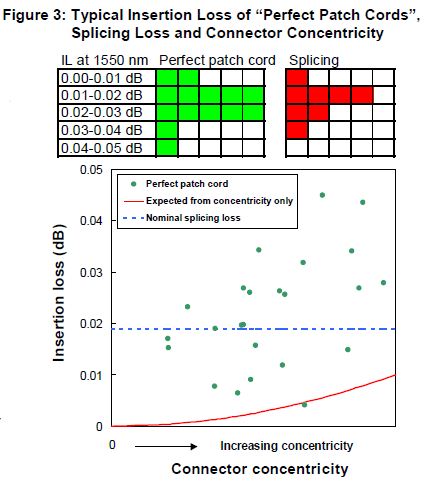
To confirm the ultimate capability of insertion loss measurement a splicing test was done with a piece of fiber. After cleaving, fiber ends were spliced using a fusion splicer. Insertion loss achieved by the “perfect patch cord” is comparable with the insertion loss measured through a splicing. Figure 3
compares insertion loss of “perfect patch cords” as a function of final connector concentricity, and with splice loss. Considering measurement repeatability and variations using the best adapters, sleeve orientations, and connector loading sequences, which can account for +0.02dB, no distinction in insertion loss was seen between a “perfect patch cord” and fusion-splicing.
Source: Panduit - White Paper – 12/2003


